|
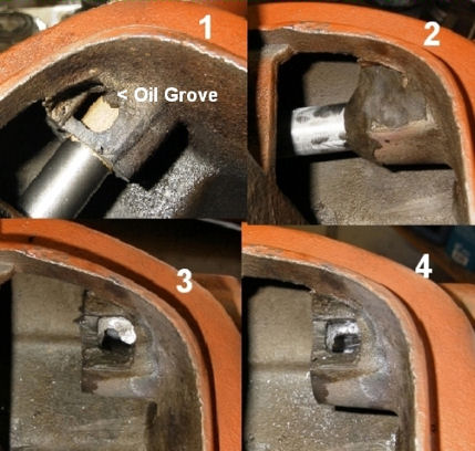
Re-Building the 702 by A.J. Wodack - May-October , 2002
One of the most popular windmills out there, the Aermotor 702 windmill is simple, quick and easy to
re-build. The parts to re-build this mill are readily available, and the replacement parts with it's exchange capabilities
means, no pouring Babbitt. That is, not unless you really want to......
Because of this, the Aermotor 702 windmill
is an excellent mill in order to get your "feet wet" for the novice, and learn the basics, and mechanics of windmills. Once
you do one, your hooked into windmillin', and can't wait to start a new windmill project, weather it's another Aermotor or
another make. The principles learned here can be applied to these other makes as well, with some slight modifications of procedures.
An
excellent book, by Mr. T. Lindsay Baker "The 702 Model Windmill" covers most every aspect of the 702. I would suggest getting
one, there is a lot of useful information there!
I would like to share my re-building techniques. Hopefully they would
be useful for the novice, and experienced windmiller alike. There are some "tricks of the trade" that aren't readily known.
I won't be delving into ripping the mill apart. The only comment I'll make here is...... Some mills come apart easy, and others
you'll have to 'work' at. Just figure on the latter, if your luck is anything like mine...... You might also want to keep
in back of your mind to remove the oil collector #520 from the hub when your tearing into the windmill.
| |
|
|
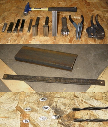
Once the mill is completely disassembled, a good cleaning is in order!! I prefer torching the cast
iron parts with a weed burner, burning the old grease and oil out of it. At times the oil will actually catch fire and eventually
burning itself out. The ash and dirt are then easily scrapped and wire brushed off. From here I sand blast the mill to have
an nice clean shinny carcass to work with. Prior to the 'burning' I melt out the Babbitt, and save it for re-pouring for this
project or others in the future. If you don't feel comfortable by burning the mill, feel free to use other options of cleaning,
like the hot tank (acid bath dipping).
With the cleaning done examine your parts, carefully. Pay ATTENTION to DETAILS!! Look at those pinions,
boss gears, hub, and mainframe, your checking for wear and cracks in the casting. More likely than not you'll be replacing
those pinion gears, pins, shaft, and of course all the Babbitt. Maybe a new set of boss gears, or other parts is in order.
You should have a good idea on what your going to need after this examination.
As far as I know, there isn't a 'spec'
sheet on the tolerance or 'play' that is allowed in building the mill. So a lot of common sense is needed here. If there seems
to be too much play in a part, there probably is.....
However, most of the guess work is taken out by purchasing a
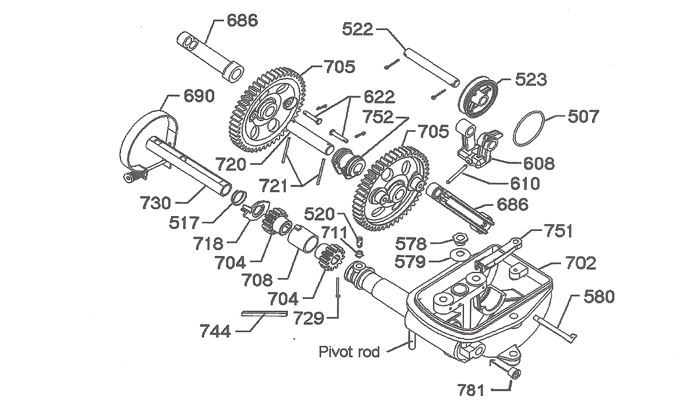
re-build kit. There are 3 re-build kits available from different manufactures.
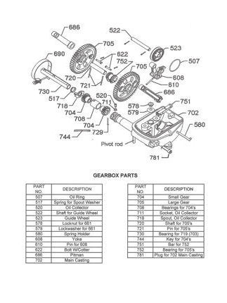
The #770 bearing kit that includes
parts #520, 708, 730, 752, 729, and two 721. (Available from Windmill-Parts.Com for as little as $75 +
shipping)
The #707 kit includes everything in the #770 kit plus two #686 and a 744. (Available
from Windmill-Parts.Com for as little as $130 + shipping)
Then there is the #777 overhaul kit which includes
the #707 kit plus a #507, 517, 522, 610, 718, 720, two 622, and two 704. (Available from Windmill-Parts.Com
for as little as $200 + shipping)
I'm not sure why these kits, especially the #777 kit doesn't include the
#510 vane pin. I have yet to see a mill that didn't need one!! So I include this part in my order.
With kit in hand,
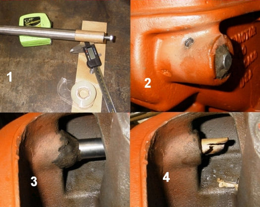
it's time to put things back together. First clean up those new parts in solvent and wipe them dry. Dry fit those new parts
onto your mill parts, paying particular attention to the pinion gears' placement onto your hub shaft. Make sure they slide
effortlessly on the shaft. If there is any score marks or 'mushrooming' at the end of the shaft, now would be the time to
take care of the problem. Not when your trying to get things together!! Everything should just slip together smoothly without
any need of a hammer to get things to fit.
The next thing I check is the pitman guide hoop, #508 for excessive looseness
or 'play'. Moving it from side to side will indicate this. Most generally all that needs to be done here is re-set the #508R
pins by 'peening' them. Worse case scenario, is you'll need to replace the #508R pins. (HINT: You may want to remove the hoop
and knurl the ends if looseness persists.)
Moving on to the boss gear assembly. The bearing, #752 needs a slight modification.
There is no oil grove or channel in the bearing, so oil dispersing is hindered at this point, I feel. As most of the pressure
and subsequent wear occurs at the bottom of the #752 bearing. Additional oil flow would help. What I do is add an oil grove
by doubling up hack saw blades and cutting a grove, carefully between the oil valley on the top end of the bearing. Just going
deep enough, about the depth of the saw blade teeth (this is a judgment call). I then use a razor sharp blade to clean up
around the oil valley and the grove I just made. Oiling up the shaft and bearing, I place these together.
Through out it's original life the boss gears, #705 were riding, basically on one side of the gear
teeth. If you reverse these gears (from left to right) you would have a new gear tooth face riding on the pinion gears #704.
In essence, it's like having a new set of boss gears to last you another 40, 50, or more years. (HINT: If you turn your hub
'clockwise' and watch the way the pinions are hitting the bosses, that will be the gear tooth side in real life.) I mount
the boss gears on the new shaft aligning up the pin holes. Because the boss gears are stationary and not free floating the
two boss gears need to be perfectly aligned with each other or else gear 'clunk', and or binding will occur. (Hint: This can
also occur if the pinions #704 are not properly aligned with the hub shaft keyway with the #744 key.) Here I use the pitman
arm long stroke boss on the gear as my reference point, with tri-square in hand I align the gear teeth on both gears. The
#721 pins are then place in the boss gears and bent over. (HINT: Bending one side of the pin in an 90 degree angle in your
vise first, will help keep the pin in place as your playing with your combinations.) If the gear tooth alignment has moved
after adding the pins, different combinations of the #720 shaft placement can be tried, for instance, rotating the shaft 180
degrees, moving from right side to left. A total of 4 combinations can be tried, alignment will work on one of these combinations.
Once that is found, bend the other end of the pin in the opposite direction so it looks like a 'Z' configuration, locking
things in place. (HINT: You might want to knurl each end of the #720 shaft after finding the correct combination to tighten
the fit between the shaft and gears. But be fore warned that you may have to use a hydraulic press to press the gear back
onto the #720 shaft.)
Moving on to the hub shaft assembly now..... I haven't had too much luck at salvaging the pinion gears
from an original mill, (maybe, I'm just too picky here) though I have come across some decent looking pinions from time to
time. Generally, I just install new ones. If you happen to get a nice set of used pinions, and want to use them, these too
can be rotated from left to right to gain a new gear tooth face if so desired.
Now mount your new bearing #708, making
sure the tang of the bearing fits into it's slot on the mainframe. Oiling up the bearing, and the pinions, place the pinions
into the bearing. (HINT: You may want to mark the pinion keyway location on the front pinion at this time with a marker. Might
save yourself a headache with the alignment, when it comes time to drive the #744 key in.) Now slide in your #730 bearing
into the snout of the windmill, this should slide in flush on the front of the snout. (HINT: If your bearing is hard to slide
in, use and adequate length of 'all thread' running it through the #781 plug hole, and the snout of the mill. With nuts and
washers of appropriate size suck the bearing into the snout. Care must be taken so you don't score the bearing with the threaded
rod.) The spout washer #718 and spring #517 are installed next, the spring going in front of the washer, the large diameter
portion of the spring going against the spout washer, and the smaller diameter portion of the spring riding against the #730
bearing. Remember when I said Pay attention to detail?? Check to make sure the tit portion of the spout washer is well past
the bearing, and the spring is 'springing'. You may need to trim off some slag of bearing material on the #730 bearing for
the spout washer to work properly. When everything looks good, oil up the hub shaft and the #730 bearing, sliding the hub
shaft home through the pinions. Install the #744 key on the hub shaft, and pinions to lock the pinions in place....... You
were able to align the front pinion keyway, weren't you?? Good!! (HINT: A little squirt of WD-40 on the #744 key helps it
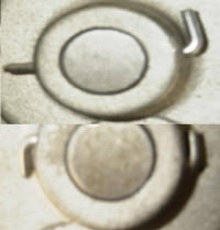
slide in a little easier.) Now install pin #729, and bend the locking pin in the rear hole of the hub shaft. There are two
type of pins that are normally supplied, a straight pin that needs to be bent in the 'Z' configuration, and the 'headed' pin,
that is bent in only one direction. (HINT 1: I find if you grind about 1/3 of the head on one side of the 'headed' pin (down
equal to the shaft of the pin), the ground head part slides nicely along the side the pinion, and it doesn't bulge out when
you drive the #729 pin home.) (HINT 2: You may want to place a slight taper at one end of your #729 pin with your grinder,
that way the pin will self align, and won't bottom out on a lip or edge, as your driving 'er home.)
|
|
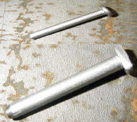
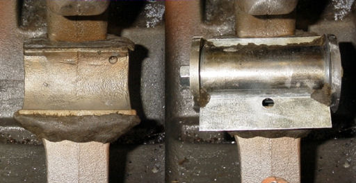
#729 Pin As Std & Modified |
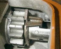
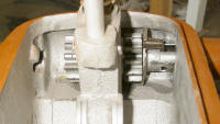
#708, #704, #718, #517& #730 |
No tricks are need in mounting the #522 pin through your yoke #608 and guide wheel #523. Just oil
'er up and put together. Select which stroke option you want, long or short, and mount your oiled #686 pitman arms. Never
split the stroke!! (Mounting your pitman arms on the long stroke large gear boss and short stroke (bottom hole) pitman arm
hole onto the #522 pin, or the short stroke large gear boss and long stroke (top hole) pitman arm hole.) Your oil ring #507
won't operate properly and the upper end will be starved of proper lubrication. Prematurely, wearing out your mill.
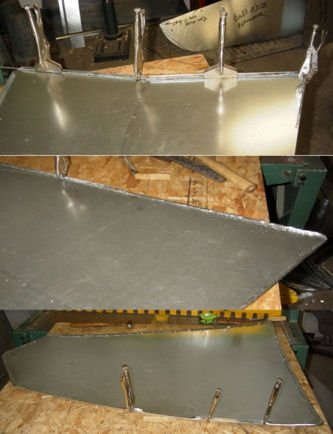
Putting
it all together you should have a nice tight, free wheeling windmill ready to work for you. One last check to make sure you
have everything put together correctly, and check there is no play between your boss gear bearing saddle #752 and bearing
bar #751. The bearing bar tang may have been worn, though this is rare, but an easy fix is at hand if it is. Using a penny
or dime (of course the date on the coin should correspond to when you put your mill together.... ;-) as a shim between the
bearing bar tang and mainframe then re-torque the bolt.
The very last thing to get installed, is the oil collector #520. That doesn't get installed until
the sails are mounted. You'll need the sails as a fulcrum to properly 'set' or 'seat' the oil collector. I just find it easier
to do it this way. Remove the pipe plug from your hub, turn your hub hole to 'high noon', as if it were the hand on a clock.
Using a wide blade slot head screwdriver, screw the oil collector into the snout of the mill. Grabbing the wheel arms of the
windmill, turn the hub clockwise about an inch or two, then counter clockwise about the same distance. Progressively going
back and forth until a complete revolution or so is made, you'll feel the oil collector seating as your doing this. Re-install
the pipe plug in your hub and your ready to go.
I have my share of derelict windmills. It sure is nice to have one come apart with ease. But there
are special problems related to the 702, which you must know for it to come apart, or even to put it together as a rebuild.
In my above article, I avoided the 'tearing into the mill'. Now I will attempt to address some of those pitfalls that
I have encountered.
The Rusted Up Tight Windmill
Sometimes you'll need to make a command decision
on what can be save, and what you may have to sacrifice, when you restore an old mill. It would be nice to salvage all of
it, but normally it doesn't work that way. Heat is an excellent way to get things apart. I've used water with good results,
by soaking the parts. Rust will dissolve in water. I've even went as far as sand blasting the part all around it's nooks and
crannies to give it less resistance to coax it apart. It just depends how bad you want to save a particular part. I've even
split a case to save a hub and shaft from it, that decision wasn't hard to make as the mainframe case was already broken.
In another situation the mainframe was good, but the hub was already broken. I ended up cutting the hub shaft and pinions
out to save the mainframe. Cutting cast iron is not the same as cutting steel, cast iron kind of melts away under a cutting
torch instead of having a clean cut as in steel. Rusted tight mast pipes are very common, here I find heat is the best way
to get them loose. Because of the large area to be heated, my weed burner works the best here, it's able to put out that large
number of BTU's to get things warmed up. With a little twist of a long handle pipe wrench, evens up the score with the rust.
The weed burner also comes in handy to melt the babbitt of the 708 and 730 bearing, especially when the hub and shaft are
rusted tight and you can't get it to turn. Melting this babbitt will give you enough play and an edge in order to get the
hub and shaft out, as well as access to the oil collector, that you couldn't get to when your hub and shaft was stuck fast.
|
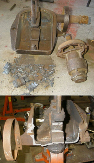
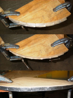
Sometimes you have to pick
what you're going to save.
|
|
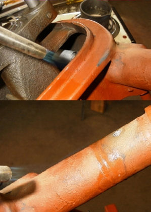
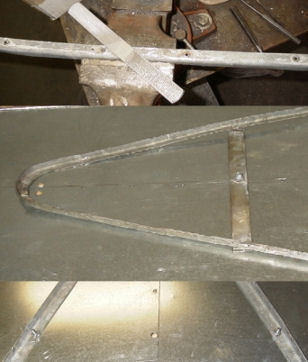
Bad Mainframe Castings
Well, maybe I shouldn't say they are bad, but attention to detail has a lot to be desired.
Sometimes there is just poor workmanship. It seems to me that the quality of the casting dating in the 1950's is the start
of the degradation of the mills. The casting is rough, the cast lines hasn't been ground off, and these are a lighter castings
in general. If you have one of these newer mills, compare it to one of the 602, or older 702's that was cast in the 30's and
40's, the difference in the quality is noticeable. You may need to get your grinder out and grind out or smooth some of the
cast lines or casting slag, which should have been done at the factory. On one of my mills I had some casting slag that was
in the 708 bearing tang. Instead of removing the slag, the builder cut off over a third of the babbitt tang to make it fit.
This is not quality workmanship folks!! It took me all of 30 seconds to clean out that casting slag. I often wonder how long
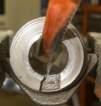
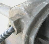
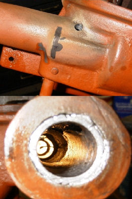
it took him to cut the babbitt tang to make it fit. Further example is an over extended cast line (see the photos), where
the builder used a hammer on the gears to get the boss gear 752 bearing to fit in the mainframe. So check your mainframe closely
when you clean it up. Look for these manufacturing defects, and take care of the problem before the rebuild. It will be worth
the extra effort.
Other
Problems
You put your rebuilt all together only to find the pinion gears are not totally locked tight on the
hub shaft. You have lateral movement of the pinion gear, and it will only get worse if you let it go. Look to see if the pinion
keyway has been widened on both the shaft and pinion gears. There are three causes; first it could be the 744 key itself.
Or either the shaft keyway is worn, or a used set of pinions were used where the keyway cut has widen from wear, which are
not locking to the shaft. You have some choices to repair the problem. Get new pinions if that's the cause. You may have to
take the pinions and shaft into the machine shop and have the keyway re-cut to the next larger size for both the shaft and
pinions. Or you may also have a new keyway cut on the opposite side (180 degrees from the original cut) of the shaft at the
correct stock keyway size. Or have the hub re- shafted. None of these options is quick and easy, nor cheap if you have to
take it into the machine shop. The end result is that pinions need to lock tight on the shaft.
Oil Collector Problems
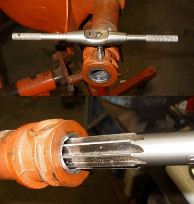
Oil collector is not fitting properly, what to do??. I assumed when you got your rebuild
kit, you dry fitted all your parts, including the 520 oil collector. You did dry fit the item, didn't you?? Did you make sure
the bottom of the oil collector is all the way down on the 711 nut seat?? You may need to chase the threads of the 711 nut
in the snout with a tap to clean those threads up. I find most all of the problems stem from the oil collector not seating
all the way down. When your on your final stage of installing the oil collector in your hub, you need to look down in the
hub hole to see where the top of the collector is. If it's standing half way up the threads of the hub hole, you have a problem,
and may break the oil collector off if you try to seat it. The best place that the top of the oil collector should be is just
at the last thread line of the hub plug hole. Remember that the oil collector needs to scrape the inside of the hub, for it
to do it's job. Keep this in mind if you decide to grind or file the top of the oil collector down a bit.
Peening and Knurling Definitions
I was told I needed to define some of the terms I used in my last article,
and explain how I performed these operations. I apparently lost some readers with these terms I used in the context I was
using them.
Peen Definition: Shaping something, generally a bolt, shaft or pin by striking it with the peen of a hammer,
mushrooming that bolt, shaft, or pin on it's end.
Knurl Definition: A series of protuberance that run along the edge of
the shaft.
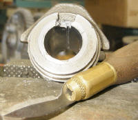
The peening definition, I thinks is self explanatory. When I knurl a shaft, for instance the 720 shaft that
fits into the boss gears. I use a center punch, and hammer, putting a series of dimples around the shaft, where the boss gear
will fit onto. The only thing you have to remember is that the 752 bearing is already on the shaft when you do this, so you
don't mess the bearing up by sliding it over the knurled section. The routine I go through is, first knurl one side of the
shaft, and press it into the boss gear. Slide the 752 bearing onto the shaft, then knurl the remaining side of the shaft,
and press the remaining boss gear on. Hopefully you remembered to align your 721 pin holes first, prior to the knurling.
Pressing out Hub Shaft from Hub
If you need to replace the hub shaft, the safest way and by far the preferred
way, is to drill out the shaft. No sense on taking a chance of putting a crack in that hub as your pressing out that shaft.
There is so much pressure on the cast from the shaft being locked down by the key and peened at the factory. Grinding the
peened part, may not relive enough pressure, that key has a lot of pressure associated to it too. Relive that pressure by
drilling out that shaft as much as possible, before pressing it out.
More Shaft Pressing
Pressing out the 721 shaft from the boss gears can present it's own set of problems. Use
a drift that is just undersized to the 721 shaft. Make sure the ridge where the 721 shaft enters the boss gears (it's hub)
is on a support. Don't lay the boss gear flat on your press and try to press out the shaft. More than likely you'll break
the gear, use that boss gear hub for the support point. If the shaft is really stuck in the gear, heat can be applied or drilling
the shaft out are other options that can be used. If it gets to this point, drilling the shaft to relive the pressure against
the cast gear would be preferable.
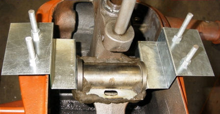
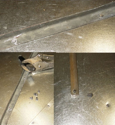
Pressing out the hub shaft with the bolt and nut through the 781 plug hole is a
rather easy and effective. I have my special bolt set up as a kit. I use a staggered sized angle iron that I place in between
the front pinion gear and the case. My angle iron is long enough, that its held in place by the bottom of the mainframe case.
The threads on the bolt would get buggered up as I was pressing out the shaft, so a slight modification to the bolt was made.
I ground the threads off the first 1/2 inch or so from the end of the bolt. This type of shaft removal works fine as long
as the shaft cooperates and slides out, but if it's stubborn, you may crack the case!! I did crack a case using this method,
luckily the case was already broken and it wasn't a big loss to me.
| |
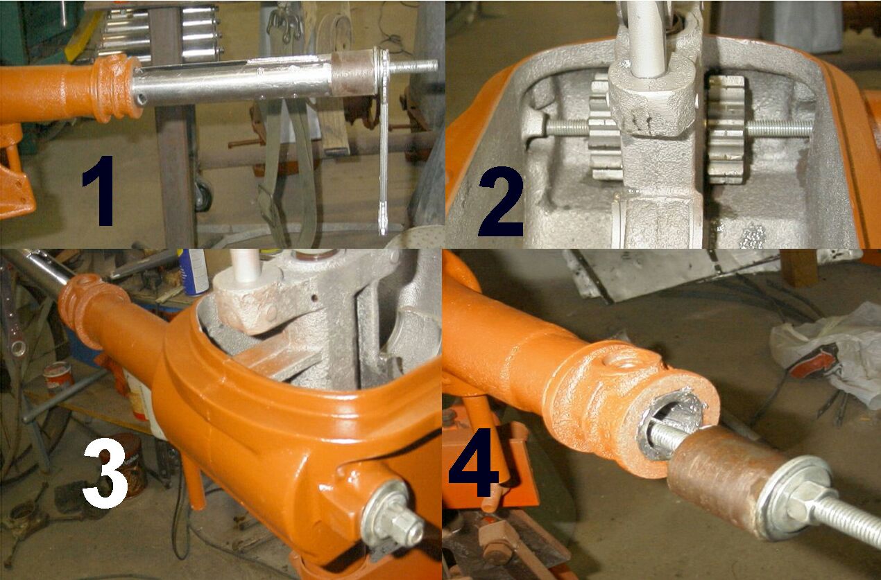
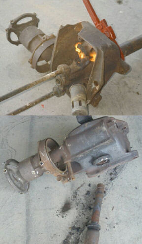
A simple to make jig using all-thread can be helpful inserting the #730. Be sure your #708 & front Pinion
#704 are in place first.
|
|
|
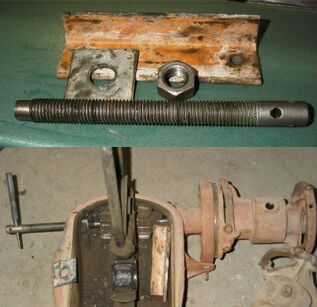
All-thread can also be used to push
the main shaft out.
|
Using this method on a stubburn hub shaft can
lead to cracking your case. Be sure your #520
oil collector has been removed first.
|
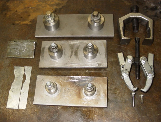
Time to Go Hydraulic??
With the cracking of the case, I figured it was time to figure a
more efficient way to press out the hub shafts. I knew hydraulics would be the way to go. But the mill motor just wouldn't
fit in my press, and I couldn't figure out a jig to make it work that way. However a portable 10T hydraulic ram could be made
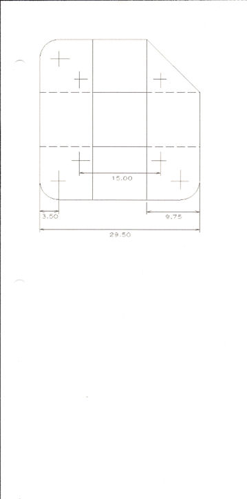
to work!! This jig plan is just in the concept stage. I haven't built it as of yet, so the measurements are not exact. I just
took rough measurements with my tape. If you are thinking about making this jig for yourself, make a cardboard template first
before putting the cutting torch to steel. The advantages to this jig is the 'pushing' power of the hydraulic ram is distributed
through out the hub shaft side of the mainframe. No more 781 plug hole breakage. No more time consuming screwing in the bolt.
More pressure can be applied to the hub shaft, so marginally stuck pinions would be an easy press out.
I figure 3/16
or 1/4 inch steel plate would be sufficient to build this 2 piece jig for the 8 footer. Jigs would also need to be made for
the 6, 10, or whatever size mill you may have, of course measurements would change and use appropriate sized plate steel to
construct the jig. The top piece jig could be further modified, by extending the plate and using a U-bolt to clamp around
the snout of the mill, like the bottom jig. I don't think this would be necessary, as there should be more than enough strength
in the pitman guide base. Like I said this is in the concept stage, so experiment with it. I know I will be!!
**************************************************************************
How I Poured Babbitt in my 602 by A.J. Wodack
-May, 2003
DISCLAIMER
This article
is how I poured babbitt in my Aermotor 602A project, and NOT on the proper way to pour babbitt. This article is not intended
as an instruction instrument to pour babbitt. I am not an instructor nor qualified in the instruction of pouring babbitt.
There are much more qualified people out there than I, that can give this instruction.
Babbitt by it very nature is
a hazardous material. Once heated to it's working state of 500 degrees plus, becomes much more of a hazard. Not only by the
fumes it produces, but in it's molten state can splatter, or even explode, causing severe injuries to a person.
My
advice to you..... Don't try this at home!! Contact a professional windmiller to pour your babbitt for you.
The Project
As
you may recall in a previous article, the "Armel Experiment", where I placed roller bearings in the snoot of the windmill
in place of the original stock babbitt bearings. Due to alignment problems with the shaft and bearings, the oil seal failed.
Thus, precipitated the replacement of the original babbitt bearings. Some viewers out there wanted to see how I did it, so
here goes......
Limitations
Please keep in mind, I've only done a few 602s,
I feel the information given here on the 602 is fairly accurate. My process of pouring babbitt is a continues adaptation and
experimentation. And because I'm a 'trial and error' type person, I've been known to do things many times over until I'm personally
satisfied.
Jigs, Jigs, and More Jigs
I've made a number of jigs
to do my babbitt pours. It sure makes my life much easier, though one can do it without the jigs, it's just a little harder
to do.
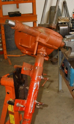
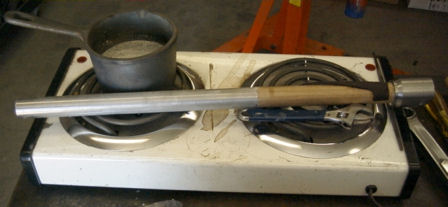
First up is my windmill engine stand. I can turn the mill motor in any direction, at most any angle, a real
plus when it comes to pouring babbitt. Being by myself, its like an extra hand or two.
|
|
One of many tilts by my engine stand jig. When doing the middle bearing the snoot needs to be almost straight
up. With the front bearing the snoot needs to be almost staight down.
|
Next is my stainless steel mandrel, stainless is a bit tougher, so it resists dings and scratches. Plus it doesn't
rust. I have a built in centering lip on the front, notches cut on each side so I can fit a 1 1/8 inch open end wrench to
turn the shaft. A drilled and tapped hole on the same end so I can screw in my slide hammer into it for easier pulling after
the pour. A 3/8 inch bolt hole on the opposite end of the shaft, used for centering the shaft on the 602 models that has the
rear saddle bearing plug. (If the 602 model doesn't have this plug, then the bolt is removed and other centering schemes are
used.) The main shaft diameter is .996 + or - .001.
Use an electric hot plate to warm up the mandrel before the pour. Don't worry....The paper won't catch fire during
the pour.
|
|
Boss bearing jig is nothing more than a boss gear set that was broken beyond use. I trimmed off the gear part,
and used a nut and bolt to hold the journal together. A couple of slits were cut into the side of the bearing journal, and
20 ga tin was used as seats that slid into these slits. The tin piece closest to the hub shaft side of the mill was cut at
a half inch, and also used as a centering guide for the main bearing journal. The other tin seat has a 3/8 inch pour hole
in it's center, and is expendable. Generally after the pour I use a chisel to knock off the overflow babbitt, and it (the
tin seat) can become a bit bent after that, and a new one is made.
|
If you use a simple jig to hold the boss
bearing jig a much finer centering
adjustment can be achieved.
|
Homemade pitman arm babbit
pouring jigs.
|
Last is the pitman arm bearing jigs, these too were made from stainless steel stock. These are zero clearance jigs,
meaning I have a .002 oversized clearance already built into the jig. As a separating agent I use WD-40 on these.
Separating Agents
As long as separating agents was mentioned...... Something is needed to break
the bond between the babbitt and it's mold or mandrel. A lot of different things can be used, and it's going to boil down
to what your most successful with, on what you use. It's personal preference thing.
A few that I've use..... WD-40,
sheetrock powder, clay dust, a rich acetylene mixture for smoke, soap stone, paper, and tape. I'm sure there are many more
items out there that can be used. However this list should give you an idea.
Jigging For The Pour
I spend more time jigging for a pour, than it takes to make that less
than 5 second pour. Centering the mandrel is high on the agenda list. Not wanting to have a stuck shaft, on multiple pours
like on this 602, I'll make each of the 3 pours separately. A separating agent is needed to keep the mandrel from sticking
to the babbitt, making for an easier pull out, and clearance purposes. Damming is another consideration one has to take into
account. Tilting the mainframe in the right position for the pour, and let's not forget about preheating the cast to get the
moisture out.
|
|
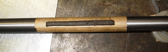
Doing a little preheat of the cast will draw moisture out that might otherwise interfere with the pour. |
Starting my jigging for the rear saddle bearing, I already knew I was going to use a grocery store brown paper
sack as my separating agent. Cutting out the length I needed, doing a tight wrap, butting the two edges together, I scotch
taped it together. Using my micrometer I found my wrap gave me .004 over on my mandrel. Perfect!! (After the pour, this clearance
figure will shrink a little as the babbitt shrinks from cooling.)
Prep of the rear saddle. If you can't get the paper out your torch will do the job. |
|
Mounting my mandrel and centering it, I lock it down with my bolt in the bearing saddle plug hole. Using Babbitt-Rite
as my damming material I plug everything but the pour hole, making sure everything is sealed. Then tilting my mainframe in
the position I needed for the pour.
Torches
Two kinds of torches that I used here for the preheat. When I do babbitt pours I find the Bernz-O-Matic
propane hand held torch to work the best. The Oxyacetylene torch kind of gets too hot too quickly and a little harder to control
the heat needed. Care must be used here. Oxyacetylene is fantastic, to melt out the babbitt on a screw up though..... I've
used both, just prefer the propane one for preheat, and propane has a clean flame to boot.
Making
the Pour
Preheat the cast, you'll see the moisture coming up to the surface. Because the cast is rather thick
at these bearing saddles, I let the heat permeate through to the inside, saturating it as much as I can. Preheating to around
100 to 200 degrees (this is a 'guess and by golly' on my part) I'm ready for my pour. Just before doing my pour, I do a mix
on my molten babbitt, then skim off the dross that forms at the top from the mixing, With the molten babbitt being bright
and shiny with no floaters, I then make my pour.
|
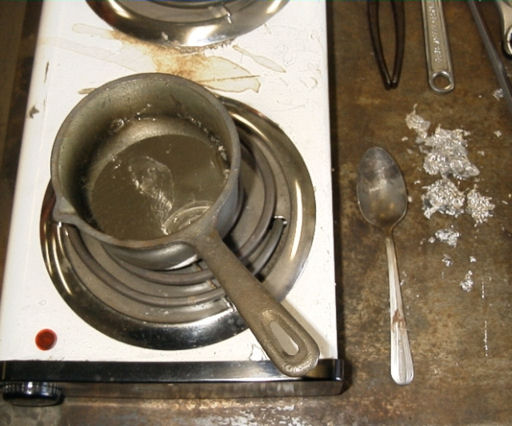
|
A babbit melting pot on the electric hot plate. A tin spoon to clean off the dross before a pour. |
Get that Mandrel Out!!
This is no time to sit back and admire the pour. You need to get your mandrel removed
from your pour!! Babbitt has a bad habit of shrinking and locking the mandrel fast if left to cool for any length of time.
Babbitt will solidify almost immediately after the pour, as soon as I feel confident the babbitt is solid, I knock off the
damming material, remove whatever I have holding my mandrel in place, and yank that mandrel out!!
Sometimes a twist
or turn of mandrel is sufficient to release it for a hand pull out, or one may need other means to push or pull the mandrel
out. Having my share of problems getting things apart in the past, I built in a couple of modifications to my mandrel. Notches
cut on each side so I can fit a 1 1/8 inch open end wrench, or crescent wrench to turn the shaft. I drilled and tapped a hole
on the end so I can screw in my slide hammer into it. Additional modifications, included separating the rear saddle bearing
mandrel, and taking an additional .005 of an inch off on nonessential section of the mandrel to give additional clearance.
Moving On
After the first pour I start jigging for my next, going through basically the same routine mentioned
above, doing some slight modifications along the way. First I clean off my mandrel and buff it up with some fine steel wool.
The first pour should be cool enough by this time to check to see if enough clearance was made. Test fitting the hub shaft
or mandrel in my pour, satisfied with the fit, I tape up a new piece of paper on my mandrel for my next pour.
You can pour 2 at a time. WD-40 works as a seperating agent. |
Use a rasp for edge clean-up. |
On the center bearing I added a 3/8 inch oil grove, made with Babbitt-Rite, down the center of my tape seam. This
grove goes from the spout washer hole snoot side, to the center cavity. The 602 doesn't have an oil exit hole like on the
702, it is built into the mainframe casting. Starting about 3/4 of an inch or so from the front of the pour hole, and exiting
into the mainframe along side the spout washer hole. If you don't know it's there, it can be easily missed. When damming,
there is somewhat of a square hole where the spout washer goes that needs to be open. Make sure you put some Babbitt-Rite
here too to keep that open.
|
|
3/8" oil groove in the middle bushing. Place it straight and on top opening in to the cavity. |
When pouring this center bearing you want the snoot almost straight up. The babbitt can easily flow into the oil
return hole as your pouring, plugging it up if your not careful. Thus, causing the oil to overflow from your hub when the
mill is running. Make sure the oil return hole is still open after you make your pour!!
The oil return hole location is marked on the outside of the case. Note the distance between it and the pour
hole. This is the reason for having the snoot almost straight up for the pour. Use a piece of wire to insure your oil drain
hole remains open.
|
|
|
Don't forget to chase the oil scraper
threads with a tap. A reamer can be
used for tight pours. The one shown
is 1.0025 in size.
|
Note the oil goove ends on the spout side.
Make sure the spout washer opening
is clear.
|
The front snoot bearing needs an oil return grove also. This can be easily made with the Babbitt-Rite damming material.
Flatten out some Babbitt-Rite to about 1/4 inch thick and using a putty knife cut out an 'L' shape piece, 3/4 X 3/4 Inch square
on the bottom part, and 3/8 to 1/2 inch wide, about 4 inches long on the top part. I've also seen it round at the oil scraper
hole, your option here. This will give you the bases for the oil return. Form this piece straight onto your mandrel, with
a VERY slight twist in a CW direction, and make sure it fits in the snoot, long enough to make it into the center cavity.
Some additional forming, flattening and trimming may be needed as you go about this process. When installing the shaft to
make the pour, make sure the 3/4 X 3/4 inch square or the round section is just below the oil scraper (# 520) hole, and centered.
Roll out a little piece of Babbitt-Rite about 3/8 of an inch in diameter and plug the oil scraper hole.
|
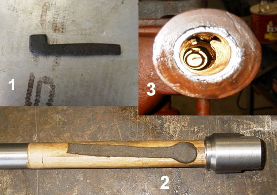
When making and installing the oil return groove
it can be square (pic 1) or round (pic3). The
groove is straight with a slight twist as shown.
|
After your pour use your hub w/ shaft to test fit
insuring everything is in order.
|
The snoot needs to be pointing almost straight down, when making this pour, or the center cavity will start filling
up.
After the pour, and things are cooled down, clean out of the Babbitt-Rite is a simple matter of using a screwdriver
to pick it out. It normally comes out in big chunks.
A Word About Screw-up's
No matter how hard one tries, blow outs will happen!! This occurred doing my center
bearing snoot pour on this project. Molten babbitt will find any hole or weak spot and breach the dam. If this breach occurs,
everything needs to be taken apart, melt out the remaining babbitt, clean it up, and start all over again. Don't make a cold
joint pour!!
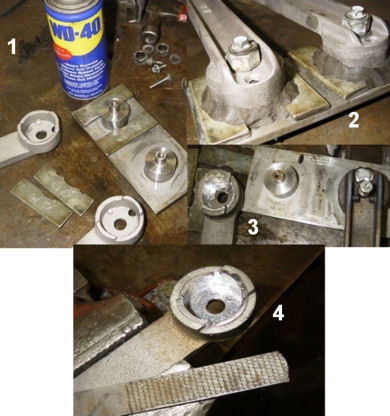
Orchestrating the Boss Gear Bearing Pour
Due to the size of this bearing, I find it's the hardest one to pour
to get a real nice smooth finish on it's surface. This is going to be a zero clearance pour, and no provisions were made for
clearance on my jig. The separating agent I used on this jig is the sheetrock powder. Because hand fitting this bearing will
be required, a real nice smooth looking surface won't matter anyway, but I do want a sound bearing to work with.
I
start off doing a preliminary jigging of my journal jig setting my tin seats, and start my damming in strategic places. As
I'm doing this, I'm also checking for centering, and the height off the mainframe cast bearing saddle. Once satisfied, I carefully
remove my jig and place it on top of my babbitt pot to preheat the jig. I also prepare my damming material ahead of time,
so all I have to do is just place it when things come together for the pour. I add a little tilt to the mainframe by adjusting
the engine stand, so the babbitt will get a little gravity assistance and flow from back to front. (The hub shaft side of
the mill being the back.) Once I start my pour, I want the babbitt to flow and fill the full bearing surface in the saddle,
and it's a large area to fill.
|
Preliminary jigging for boss gear bushing. Preheat
each piece before you pour.
|
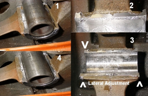
Fit the journal (pic1). Top egdes need to be
knocked off (pic2). Lateral adjustment needs
to be checked.
|
With torch in hand I start preheating the mainframe cast bearing saddle. Here I want to add more heat than normal,
maybe more in lines of 300 + degrees. Once there, it's a mad dash scramble to get everything together and dammed, then ending
up with babbitt melting pot in one hand and the torch in the other. As I'm doing the actual pour the torch flame is concentrated
around the pour hole of my jig, flame licking inside and out, right to left, during the full pour. I want to keep the BTU's
high and even throughout the pour.
Using a hammer and chisel, I knock off the babbitt overflow from my pour hole, remove my damming, and loosen the
nut and bolt on my jig. I then pop my jig off the pour. When things cool down I start fitting the regular boss gears to the
new pour. Using a rasp for the high ridges and the right and left edges (lateral adjustment sides) of the bearing. A tin scraper
with a very slight burr to even and level the bearing surface, adding a little clearance in the process. Basically doing a
custom fit for the boss gear journal. As a final process I use some fine steel wool on the bearing.
|
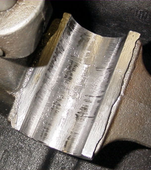
Allow the pour to cool before fitting your
boss gears.
|
Turn your boss gears in the bushing saddle. You'll be able to see any high spots that may need to be scraped
for proper fit.
|
Pitman Arms
Though I didn't re-pour my pitman arms on this project, it's rather straight forward, and think
you can get a good general idea on how it was done.
So there you have it buckaroos, this is how I poured babbitt in
my 602... *******************************************************************
Skinning An Aermotor Vane by A.J. Wodack
-May, 2003
Skinning The Aermotor Vane
As your looking at your restoration project, that vane may have seen it's better days. Full of bullet holes, rusted
up, or bent up beyond use. Maybe you have a lead on a replacement vane, but nice vanes are hard to come by. There is another
option open to you.... Replacing the skin of your vane....
One nice thing about the Aermotor vane, is it hasn't changed
much through out the years other than the general shape of it. The wishbone, vertical stabilizer, and the wire bead, all can
be used on the different shapes without modification to these items.
Workmanship
The
standard Aermotor vane, I feel has some design and workmanship flaws. For instance the upper corner portion of the vane that
was seamed together. Here I find they rusted out or broke apart on the folded seam edge.
The wire bead wasn't totally
rolled around the wire, and the tin was just folded over. But there is a plus side to this fault, when you salvage the wire
from an old vane, that wire is well galvanized because of that gap. And it's easy to pry up on this lip to get to that wire.
The
other thing is the rivets on the wishbone is just 'set' and not finished by rolling the head of the rivet. Trivial, but still
bothersome to me.
Though this vane is still structurally sound, it's these little details that show the Aermotor Company
was cutting corners, and/or workers didn't have pride in their workmanship.
In sharp contrast the Aermotor swallow
tail vane is very nicely done and finished, with rolled wire bead, and tinners rivets finished with heads. A definite quality
in workmanship pride here!!
Making a New Vane
Basically your just putting on a new skin, and using the 3 major parts, wishbone, stabilizer,
and wire. These items you want to salvage from your old vane. Then it's just a matter of tracing out your old vane onto the
new tin and cutting it out. I use 24 gage tin for my vanes. At this point your going to have to decide if your going to keep
the upper corner as a separate part or just incorporate it as a single vane.
I've made templates for doing it both
ways, depending on personal preference.
|
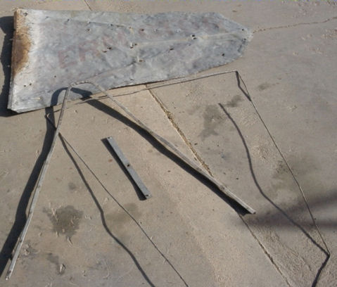
Salvage essential parts from your old
vane. grind the rivet heads off to remove
the wishbone.
|
Use your old vane to create a pattern. 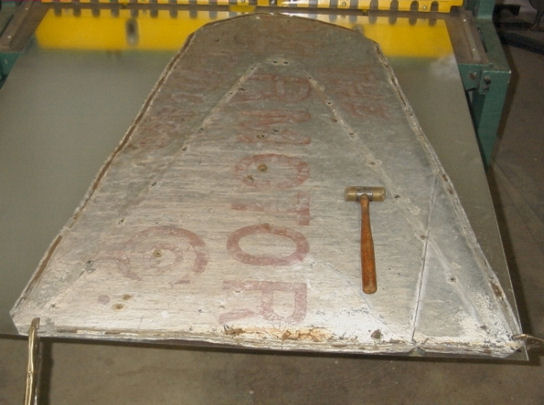
|
The next decision is how your going to make your wire bead fold. If your going to roll the tin over
the wire, then your 90 degree bend around the edge will be at the 1/2 inch mark. If your just going to fold the tin over the
wire, then you need to make your bend at 5/8 of an inch.
The Swallow Tail
The 3 salvaged
parts of the standard Aermotor vane are the same as the swallow tail vane, even down to the length of the wire. Which is nice
to know.
The swallow tail vane is cut with two parts, both halves being the same. HINT, HINT here..... use your template
to draw out both halves separately. If you cut out one of the halves, and use it as the template for the next half, you may
compound a mistake that was inadvertently placed in the first.
26 gauge sheet metal works best as a template. 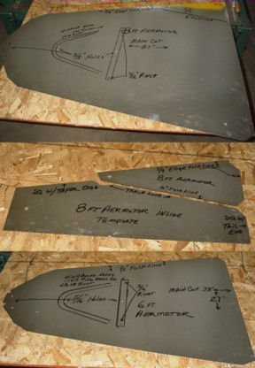
|
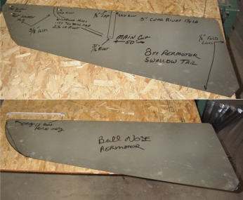
Templates shown of the common Swallow
Tail style and the early Bull Nose
type vane.
|
The swallow tail has a 1/2 inch lap in the center and 1 1/4 pound rivet on 3 inch centers holding
these two sections together. Measurement is taken from the front of the vane. (Don't forget to add 1/2 inch to the first measurement
to make up for the 90 degree bend.) And skip rivet placement at the vertical stabilizer, and crouch of the wishbone, at the
same time keeping that 3 inch center where rivets were skipped.
Layout of the two halves with the front of the vane
to your left. Bottom half center line is on top of the top section center line at the 1/2 inch mark. Rivets are centered at
the 1/4 inch mark. Punch or drill 1/8th inch holes where your rivets will go, but don't rivet yet, you'll need to make your
1/2 inch 90 degree bends first for the wire bead. Make sure when you punch or drill your holes they are exactly in the same
place between the bottom and top vane halves, or the vane will warp or ripple when riveted together.
Make your 1/2
inch 90 degree bend around the edge of each vane section. Then it's rivet time.... Flipping the top vane section over, place
a 1 1/4 pound rivet in each hole and using a little strip of masking tape, taping the rivet head in place. Flip that top vane
section over again and mount the bottom vane section over the rivet stubs. This is where you'll see how accurate you were
on your hole placement when you punched or drilled your holes.
Riveting
You'll need a solid
surface or a bucking bar placed under the rivet head. Using a rivet setter, (or you can make your own out of an old shaft)
first use the hole part over the rivet shank to draw up the tin to the rivet head with your hammer, then 'set' the rivet with
a sharp blow on top of the rivet shank again with your hammer (without the rivet setter tool), don't miss, or you'll ding
your tin. Then finish off the rivet with the concave section of the rivet setter and your hammer, (this too can be made from
an old shaft, by drilling slightly with a drill bit.) giving that nice finished rounded rivet head. You'll work up a rhythm
as you go along.
Tinners Rivets VS Pop Rivets
Not only is the structural integrity of the
pop rivet not sound, it makes your project look cheap and cheesy with their use. Kind of makes people wonder, what else was
scrimped on in the project.....
Every item that has come through my shop with a pop rivet repair had failed. I would
personally rather see nuts and bolts used, than pop rivets. Aesthetics counts too, so I would say, do the tinners rivets.
They are rather cheap to purchase, like 4 bucks for a pound box, and not hard at all to install.
Brad
Point to the Rescue
Hopefully when you were laying out your vane, you marked the hole locations for the tail
bone and U-bolts. There is a problem here, getting a nice round hole. Most of these holes are beyond the capabilities of the
hole punch, and using a standard metal drill bit leaves a lot to be desired. Generally screwing up the tin, as the tin catches
within the spiral and starts walking up the drill bit, as your about ready to punch through.
Though made primarily
for use on wood, the brad point drill bit works nicely on the soft sheet metal tin. You do need a light touch, and only enough
pressure for the edges of the bit to cut the tin. Too much pressure, and the tin will climb that drill bit shank too. If done
properly, at a very slow drill speed, that brad point will spin a disk for you, and you'll have a nice round hole in your
tin.
|
Some home made tools that prove useful. |
Take your time laying it out. 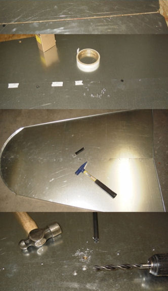
|
Okay, after a couple practice runs drilling through some scrap tin, your ready to do the real thing
now.....
The reason we waited this long to drill these holes, is especially meant for the swallow tail vane. The two
halves have to be together in order to drill the tail bone hole, as you'll be going through two pieces. Actually the U-bolt
holes can be done at anytime.
Stringing Some Wire
The next step in the process of making
the vane is string the wire, around the vane's edge. Your not going to get a perfect match where the bends are in the wire
compared the where the bends need to be in the vane. Besides you'll have an extra bend on the swallow tail in the 'V' part
of the vane if your making that vane. It's much easier to straighten out the wire, and make the bends when you come to it.
I
start off at the lower right part of the vane with a short 12 to 18 inch section of the wire vice gripped to the bottom of
the vane, making my first bend, going up along the backside of the vane. Clamping the wire in the pocket of the 90 degree
bend with vice grips as I go along. After a short distance, I then proceeded to fold the tin over the wire with my hammer,
being careful not to ding my flat tin in front of the fold. Working my way completely around the vane.
|
|
A visual hint on creating a nice edge on the
Bull Nose. Not the layering.
|
Forming the Bead
Though I do have a wire machine, I found it almost impossible
to use on the Aermotor vane. First up, the size of the vane is real hard for 1 person to handle, as your feeding it through
the machine. Then you can only do one side at a time, having to release your adjustments, and re-adjust it to work on another
edge. Even to make a 2nd or 3rd run on the same bead, you have to go through this process.
I ended up making some of my own hand tools to make the beads (see picture). One of the tools is a roller that
I made, the handle being an Aermotor 702 bearing bar (#751). The other two tools were made on my lathe with a 1/4 inch bull
nose end mill. One with a loose fit, to get the tin started around the wire, and the other with a tight fit to finish wrapping
the tin around the wire. Even using these hand tools makes quick work of the bead, with some really nice results.
Wishbone Placement
Doing the wishbone can be tricky at times, but first clean off any caked on galvo with
a rasp on the back side. Don't need any mounds holding us back when we rivet it to the vane.
Next bolt the vertical
stabilizer to the inside of the vane through it's center hole. Place a mark on the vertical stabilizer indicating which end
is going to be up. Not all vertical stabilizers were created equal, and when you go to rivet it to the wishbone, you'd like
the holes to match when it becomes time.
Smooth the edges of the wishbone before
attaching it.
|
Rivets are set then finished attaching the
wishbone and vertical stabilizing girt.
|
Now lay your wishbone over the vertical stabilizer, lining up the holes with it and the stabilizer.
You want to line up the center of the wishbone with the small U-bolt holes, and the ends of the wishbone equal distance on
the large end of the vane. During this process your keeping the holes aligned with the vertical stabilizer. Once your satisfied
with the alignment, mark your tin through the vertical stabilizer end holes. Remove the stabilizer, and drill your 3/16 in
holes at your marks.
Using a large headed machine screw, bolt down your wishbone to the inside of the vane. (without
the vertical stabilizer) This will hold down the wishbone to the tin, as your riveting it there in place. The rivets used
here is the 2 1/2 pound rivet. You want to start riveting between the hold down screws of the wishbone towards the center
small U-bolt holes part of the vane. Then working in the opposite direction of the hold down screws. Minor adjustments can
be made as your working your way to the ends of the wishbone.
A little hint here.... When riveting the wishbone to
the tin, drill one hole at a time, and set a rivet before moving on to the next one.
After your wishbone is riveted
in place, remove the two hold down bolts, place your vertical stabilizer on the front of the vane, bolting it in the center
hole again. Now, you do remember which end was up.... right?? Using 3/16 inch X 1/2 inch long rivet, align your holes and
rivet the vertical stabilizer to the tin and wishbone.
Bull Nose Vane
The Bull Nose vane
is nothing more than a swallow tail vane. Accept for the round nose. It goes through all the same process on going together
as mentioned above.
When making the Bull Nose, the swallow tail was used as a pattern. However instead of cutting a
straight line on the front portion of the vane, a trammel circle marker was used. It's also interesting to note that the centerline
for the circle is the same vertical centerline for the small U-bolt hole along the edge of the vane. It's also interesting
that it takes the same length of wire as in the standard Aermotor vane. Hmmm.... Any correlation here??
When cutting
and forming the round nose I layered the tin, kind of like the shingles of a house. So that the water would run off the bead,
instead of seeping in. Not sure if they originally done it that way or if it was really needed, but hey..... that's the way
I did it.... seemed logical to me.....
After making the Bull Nose, I now know why Aermotor went to the straight line,
it uses today. The Bull Nose vanes were much more time consuming to make.
Logos
Your vane isn't complete until it sporting the Aermotor logo!! Other
than the general design of the logo, there are some subtle differences in the actual characters that make up the logo. I sometimes
think that every person in the factory had a hand in making the logo at one time or another.
The front side lettering
style is different than the back. Some had nice oval 'O's and others had squatty square style 'O's. Periods in different places,
or none at all. Words like 'THE' missing completely from the logo, and the list can keep on going.....
|
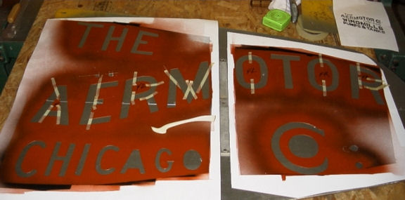
Stencil in place ready to paint. |
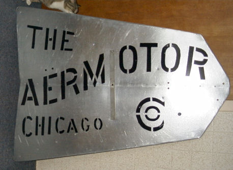
Ready to dust off and mount. |
I've made up some actual full size logos, taken from actual "nice" readable vanes that I had. Incorporating the
most common differences between the logos like period locations in the logo drawing. So when you cut out the logo you can
use one or the other, for your personal preference.
On the 'Stencil' style 8 foot logo for the swallow tail, the connecting
lines was designed from an actual picture of an Aermotor logo painted on the side of an Aermotor oil box as seen in the Windmillers'
Gazette, Summer 1994 issue, page 9. I felt this logo style had much cleaner lines, and used it on my vanes.
While the results of skinning your own vane can be rewarding, it is a time consuming
process and without proper tools it can prove to be a frustrating project. See our New
Repair Parts page as we offer a superb logoed Chicago Aermotor Reproduction Vane for
your A-602 or A-702 for $169 + shipping or plain ones for $102 + shipping.
|